June–July 2024 Development Update
Category:
We had intense progress in the Topola PCB router in the last two months. We have finished implementing five new features in total: Specctra SES export, Undo/Redo actions, command history import/export, command-line application, and advanced debug visualization.
Let’s explain what these features are.
Specctra SES export
Implemented by Tomasz Cichoń (tomec) starting in commit 7d9bf1346a.
Topola can now save autorouted tracks to files in Specctra SES format, which together with the Specctra DSN format forms the de facto standard for data interchange between PCB design and autorouting software.
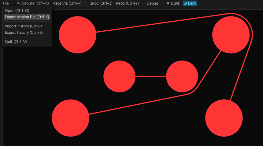
This means that you can now actually start using Topola to autoroute boards! Here’s a screenshot from a simple example KiCad project that was exported to a DSN file, autorouted in Topola, and then had the new tracks imported back as a SES file:
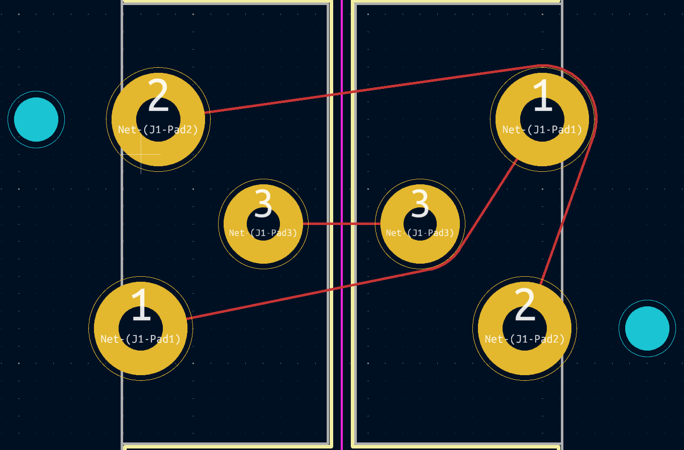
If you would like to try this out, please follow our Installation guide. Mind that currently the only way to install it is to build it from source. And many basic features are missing, as we are still far away from our first alpha release.
Undo/Redo actions
Implemented by Mikołaj Wielgus (mikolaj) starting in commit 4a4f18f558.
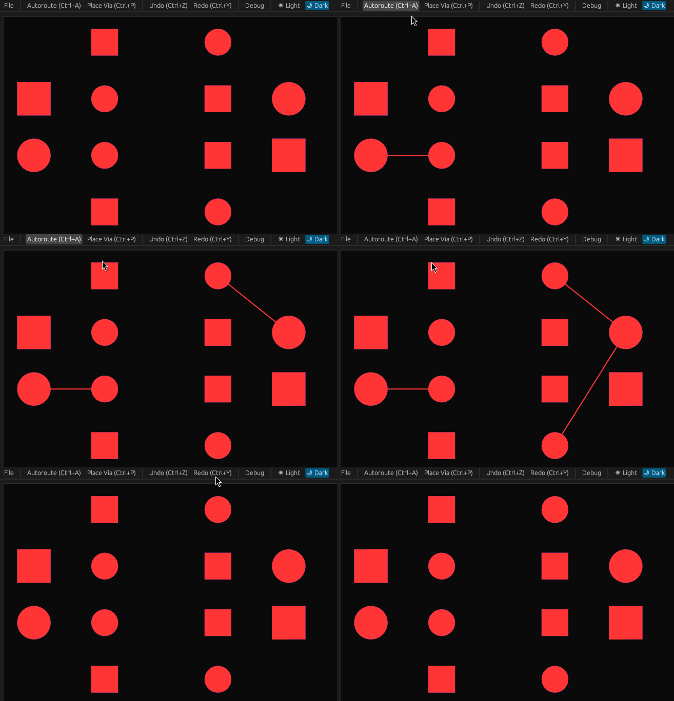
One of the basic features expected in a GUI for any kind of design software is the capability to undo latest operations one by one in reverse order, and afterwards possibly redo the undone operations individually in the original order. We have implemented this in Topola too:
Command history import/export
Implemented by Mikołaj Wielgus (mikolaj) starting in commit 02bfe1105b.
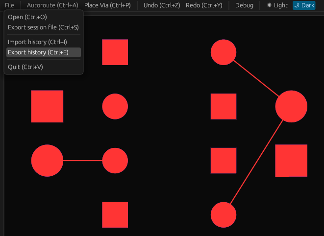
Besides undoing and redoing commands individually, the whole history of the previously executed commands can be now exported to a file. Such command history file can be later imported back in Topola and replayed. This can be helpful if your workflow requires repeating the same autorouting job.
Command-line application
Implemented by Klaudia Kołakowska (Szpachlarz) starting in commit 8d2db0a0dc.
In automated workflows, it is important to be able to run and parameterize software from a command-line environment. A program invoked from the command-line is further expected to be able to run headlessly, that is, capable of running on a system without graphical environment.
To make it possible to use Topola in automated workflows, we have
implemented a command-line
interface (CLI)
application, topola. Just like our GUI application, it takes a
Specctra DSN file as an input, and outputs a Specctra SES file. For
example, if your PCB design software exported you a DSN file named
board.dsn, running
topola board.dsn
will autoroute all nets in your design and will output a SES file board.ses, which you should be able import back to your PCB design software.
To have finer control over the autorouting process, for example by
having the tracks routed in a specific order, you can provide a command
file for topola to execute via the --commands option. This will
override the default behavior of autorouting all nets. Any command
history exported from Topola’s GUI application is a valid command file
you can use with this option.
For instance, if you previously autorouted a board board.dsn in the
GUI and then exported your command history to a file named
history.cmd, running
topola board.dsn --commands history.cmd
will replay the same autorouting job and produce the same SES output as the GUI application previously did.
If you would like to try our CLI application out, please follow our
Installation
guide.
Just like in the GUI application, many basic features are still missing
and it is currently only possible to install by building from source.
Fortunately, building topola is fairly easy.
Advanced debug visualization
Implemented by Mikołaj Wielgus (mikolaj) starting in commit ee6eeac6d8.
Controlling any complex and multilayered process — such as autorouting — greatly benefits from a means to inspect the state of each of its functional layers. One way to provide such inspectability is to have an overlay that shows the internals of the process as it goes. For this reason, we have been maintaining a debug visualization overlay to display Topola’s autorouting job as it unfolds.
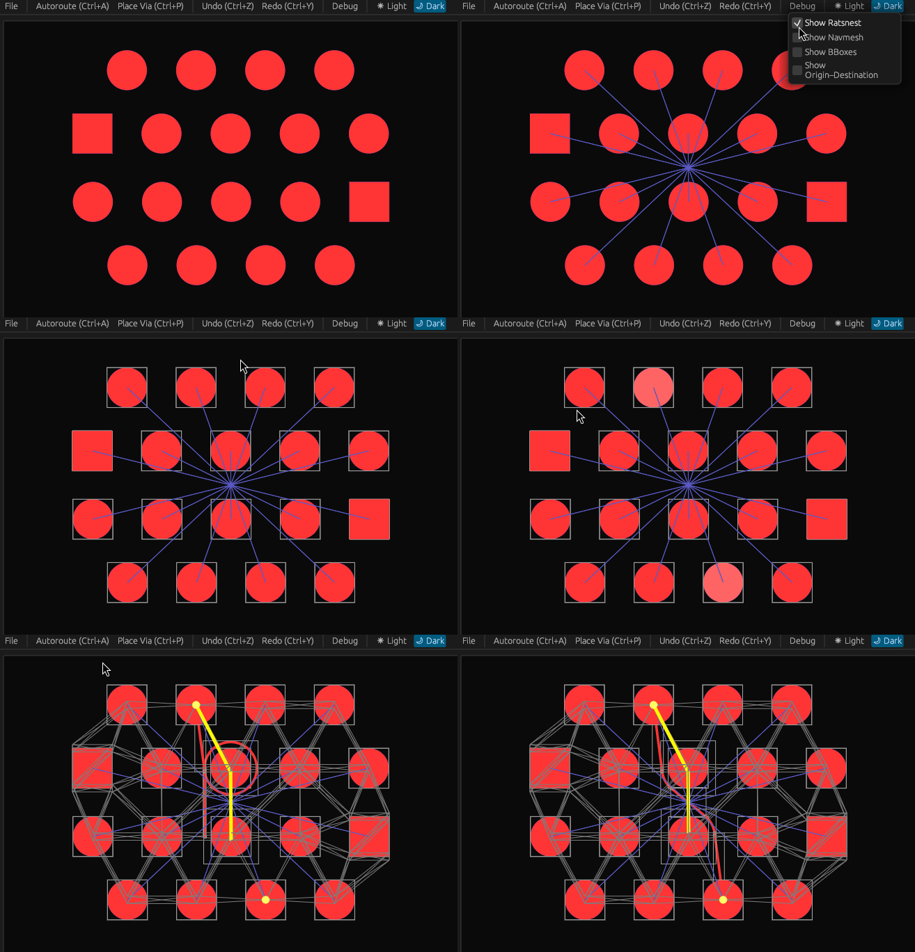
This is how the overlay looked like in the past:
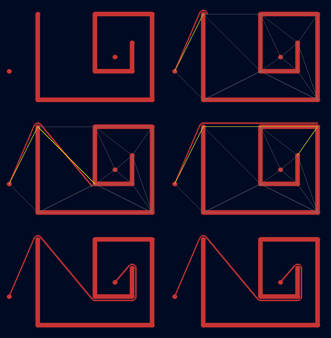
We have recently improved the overlay to display the attempted routes, which we call probes. If a routing step fails due to a probe causing a design rule violation, its clearance area is displayed instead in blue, and the infringed layout primitive is highlighted. This helps to see why the router chose one particular path and not any other.
Very often a routing step can be done in two ways: clockwisely (CW) and counterclockwisely (CCW). To distinguish between these two orientations, we now split each vertex on the navigation mesh into two where it matters. On the overlay, the vertex corresponding to clockwise orientation is shifted slightly upwards, and the vertex corresponding to counterclockwise orientation is shifted slightly downwards.
Additionally, the overlay can display bounding boxes.
The resulting new overlay looks as follows:
